
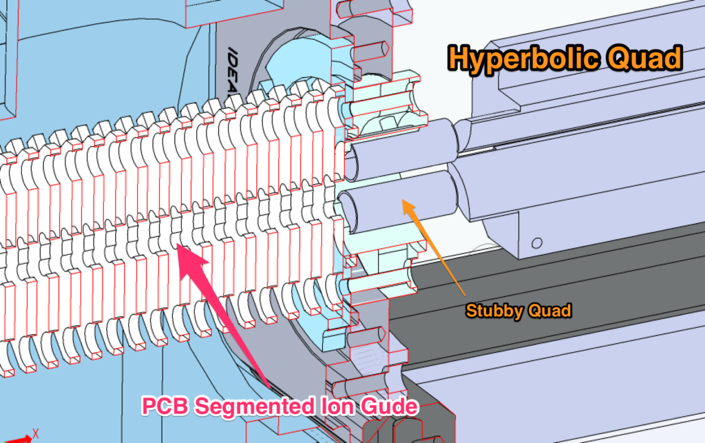
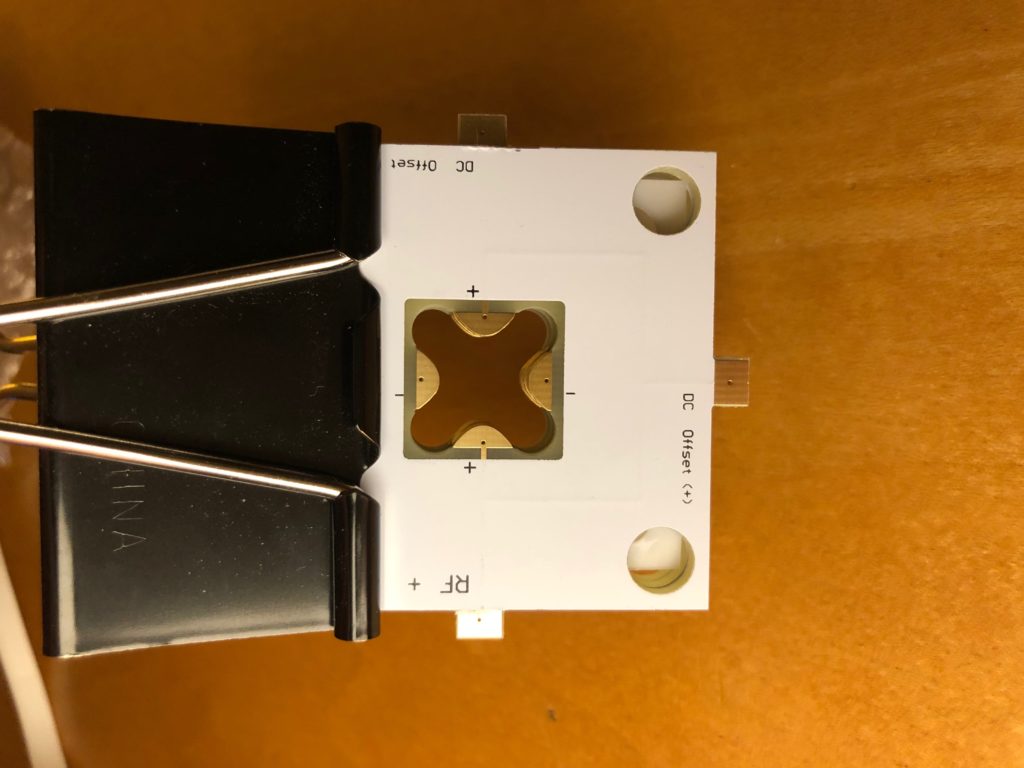
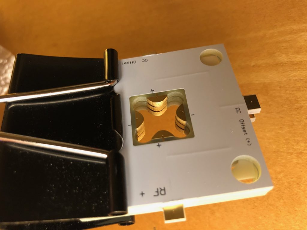
Recently we’ve been working on the design and construction of a new instrument build centering around a quadrupole mass spectrometer as a detector for ion mobility spectromety. The primary motivation is to monitor the arival time distributions (ATDs) for specific ions without the duty cycles limitations of TOF system. In many ways this may concept may be counter-intuitive, however, though TOF systems are quite fast (operating into the kHz range), if they are used as sampling devices for drift tube IMS separations cycle times in that approach 10 kHz only allow sampling of the IMS domain every 100 microseconds. When placed into context of higher resolution IMS experiments such sampling rates are largely inadequate for capturing enough points across the ATD. While we surely have not solved this problem fully, the current build needs to shuttle the any ion packets efficiently towards the detector. Stated differently, any delay in getting ions to the detector aids contributions to peak widths from diffusion–this we want to minimize. Below are a few sketches of the target build in Solidworks and the newly arrived segmented quadrupoles. Key things to remember is that this design is not aimed at a resolving quadrupole but rather one focused on ion transmission. Also, the great technical notes at Ardara Technologies would suggest that a simple rectilinear quadrupole would be sufficient for ion trasport but we simply wanted to explore this possibility.
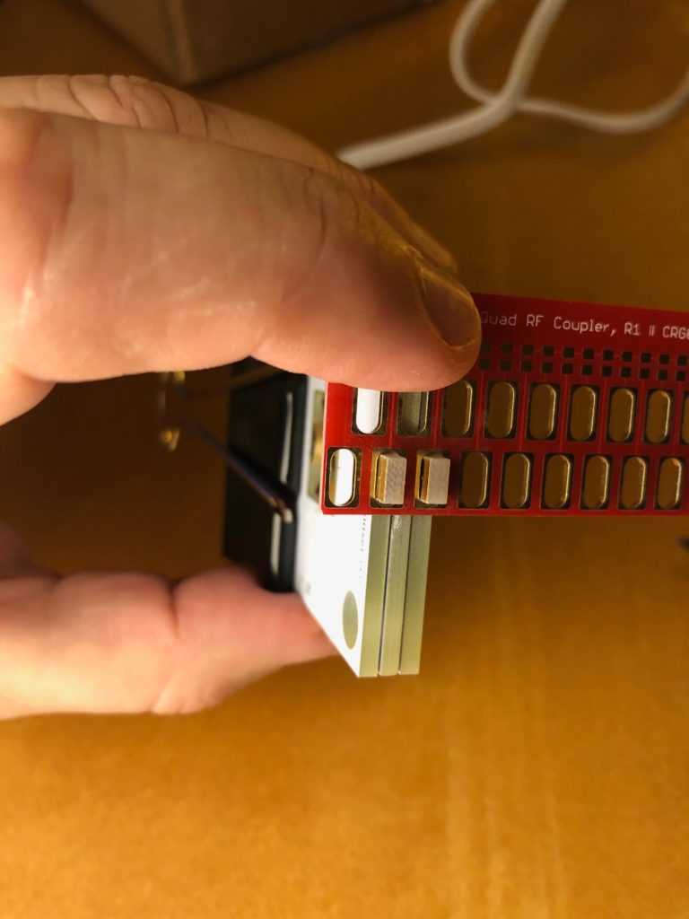
Building upon some of the ideas at the Rowland Institute we had some of the segments comprising the higher pressure quad manufactured along with the necessary coupling board. The coupler depicted corresponds to the one-half of the RF signal needed to power the setup. Stay tuned for the results on the implementation. For those interested in the actual files (still a work in progress) hop on over to github for the files.
Comments are closed