TL/DR — Code and wiring diagram to output a simulated spectrum WITH noise on a specified microcontroller output pin. Requires hardware interrupts which simulate a gating pulse.
When developing new approaches to signal processing or simply designing a new data acquisition system, having a reasonable reflection of the target signal is helpful during the development/testing stage. In an effort to supply the community with such a resource, below is a set of arduino code that is designed to output a simulated spectrum from a microcontroller following a hardware interrupt (i.e. a gate opening event). Using the variables in the code it is possible to space the output of the sequence. Though a standard arduino (e.g. 16 MHz clock) may be able to simply output the spectrum, if we want to add a level of random noise a call to generate a random integer is required. In that case a few extra clock cycles are necessary to generate such a number. For such a situation, a slightly faster clock speed is warranted.
The Adafruit WICED is an entirely capable little beast that fits the bill. In addition to sporting a WIFI chip and an additional flash module, this unit boast a 120 MHz ARM Core 3 processor. When considering the target goal (i.e. hardware simulation of an IMS spectrum), that speed comes in handy. More specifically, the code below illustrates that after each interrupt the next element in the simulated spectrum is output BUT it includes and extra call that generates a random integer that is added to the spectral element. The net effect is that a spectrum with a user-defined level of noise is output. When combined with a scope or data acquisition system, the impact of signal averaging can be explored.
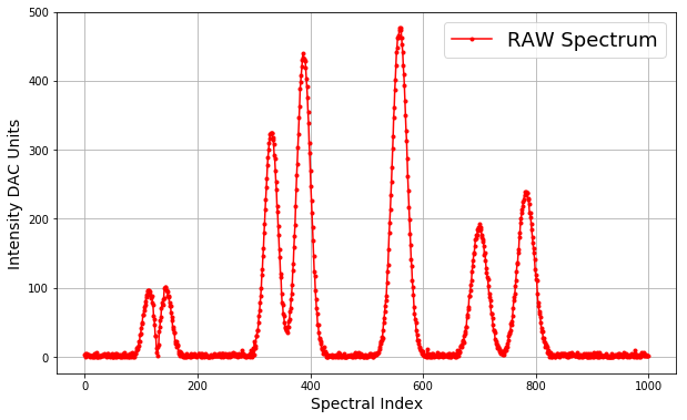
To aid anyone interested in adapting the arduino code a sample spectrum from raw spectrum is provided along with output from the WICED platform with added noise. Additionally, a wiring diagram is provided though be sure that the input trigger is not too large as to overload the WICED input levels. For reference, we are a big fan of the Digilent Analog Discovery units as they provide a wide degree of functionality (i.e. two 100 MS/s ADC inputs and two 100 MS/s DAC outputs), an intuitive graphical interface, and the capacity to script the data acquisition.
Updated 2/27/2019: Here’s a video used to demonstrate SNR scaling for WSU’s Instrumental Analysis class using the output from the posted code.
Raw Simulated Spectrum:
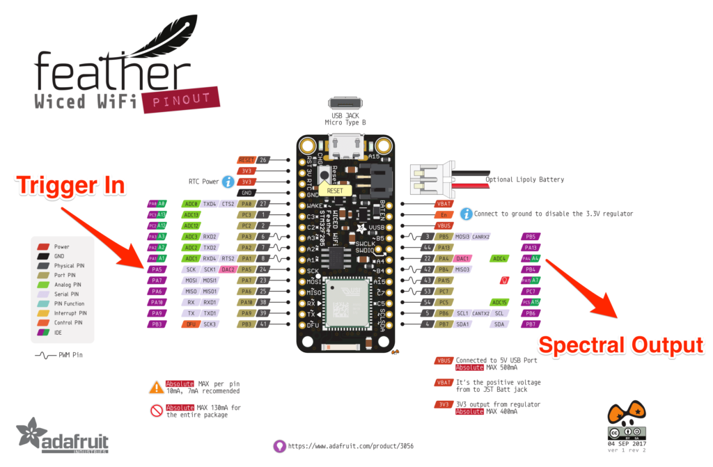
Wiring Diagram:
PA5 is the interrupt pin (Trigger In)
A4 is the simulated spectrum out (Spectral Output)
Arduino Code for WICED Feather Platform
int irqpin = PC5;
int ledpin = BOARD_LED_PIN;

#include <libmaple/dac.h>

volatile int ledstate = LOW;

int spec[1000] = {3,4,0,4,3,1,3,3,0,1,1,2,2,0,2,0,5,0,3,1,7,0,0,0,1,1,2,0,2,1,1,3,1,3,3,4,3,1,0,2,5,5,2,1,0,2,3,3,0,4,0,0,1,1,4,0,0,5,3,1,1,2,3,0,0,2,3,0,4,1,0,6,1,0,1,1,3,0,0,3,4,3,0,6,1,0,1,5,0,5,4,9,12,11,15,16,23,22,32,33,41,48,50,61,61,68,73,75,80,90,86,94,97,96,96,94,90,85,86,89,78,75,60,54,46,30,30,13,6,1,14,18,37,43,53,57,71,78,76,83,85,99,101,101,96,97,95,88,89,86,78,74,74,64,58,53,40,43,35,36,20,23,23,15,18,16,8,4,8,2,6,5,2,1,3,0,1,0,2,0,0,5,1,1,2,2,0,2,4,0,3,1,2,1,5,2,1,2,1,0,2,4,4,2,3,5,0,0,4,1,1,0,2,2,4,1,1,2,0,0,0,0,1,3,1,2,0,1,2,1,4,2,2,3,1,2,2,2,4,1,4,0,3,4,4,0,5,2,3,2,4,1,2,1,0,1,4,0,2,5,2,3,2,5,7,2,5,1,1,3,3,0,1,4,2,3,2,1,4,10,1,4,1,3,0,2,2,0,1,1,1,2,0,5,3,10,2,0,10,12,3,22,13,16,30,30,38,38,49,60,67,78,88,99,118,126,146,157,179,193,213,228,245,258,278,289,300,309,317,322,325,324,325,318,315,308,292,287,270,254,242,218,211,189,176,155,144,121,116,92,78,75,62,60,50,44,42,38,39,35,43,44,51,54,66,71,83,92,105,125,135,159,175,191,218,243,263,280,303,323,346,362,388,398,407,420,430,440,434,432,430,429,419,403,391,376,354,339,310,295,270,247,226,208,188,168,146,124,117,97,84,71,63,47,47,36,28,25,22,20,11,12,10,4,14,5,4,8,0,5,0,0,2,1,1,1,2,2,3,0,2,0,1,1,1,0,1,3,0,2,0,6,4,3,0,2,0,2,1,0,4,0,0,0,0,2,2,2,1,1,1,3,1,2,0,0,3,1,1,6,0,4,1,1,2,3,6,0,3,4,1,1,3,0,2,0,0,1,3,0,0,0,2,2,2,2,4,4,1,1,3,0,0,1,4,3,4,4,3,5,6,6,11,14,22,19,24,29,27,38,49,56,66,74,82,89,108,123,134,156,180,194,213,235,253,275,301,319,347,361,387,402,422,441,448,463,463,465,476,473,476,473,463,452,441,422,409,393,370,350,328,313,287,261,241,217,199,178,162,141,131,110,101,90,73,62,55,50,38,32,24,24,20,15,13,9,9,8,4,8,3,2,2,2,3,0,2,0,11,5,3,3,0,2,0,5,0,4,1,0,2,1,2,1,1,1,7,4,0,2,1,2,1,1,4,0,4,3,1,1,2,3,1,2,2,5,0,4,3,0,0,2,5,4,1,1,0,1,4,0,4,10,6,2,6,8,16,15,14,17,22,24,21,30,33,37,44,44,57,61,69,72,89,89,96,105,110,124,131,139,149,151,161,170,171,176,177,185,188,183,192,188,184,187,177,173,170,167,160,148,151,139,129,122,115,113,103,92,87,82,74,63,62,56,46,38,38,35,25,23,19,13,18,14,12,8,11,6,4,6,8,3,8,3,6,10,11,15,9,14,19,24,30,33,35,38,48,47,51,60,71,82,87,92,102,110,124,135,136,151,156,174,179,195,200,208,214,219,224,228,234,239,236,239,237,237,228,229,221,209,208,202,192,184,174,165,157,151,141,126,119,113,110,92,78,74,65,63,57,50,41,37,37,28,27,23,21,14,17,16,14,6,4,10,0,4,3,7,0,0,2,3,2,3,0,0,1,1,5,4,1,2,0,1,5,4,3,5,2,5,3,4,1,1,3,0,1,4,0,5,4,4,2,6,2,3,3,3,3,1,1,1,1,6,4,0,1,0,1,2,3,1,0,0,2,4,1,2,2,1,4,0,0,0,4,3,0,5,0,1,2,0,2,7,0,1,3,5,0,6,4,0,0,7,3,2,2,2,2,0,2,1,1,2,2,5,0,0,2,0,0,0,0,0,0,4,0,0,2,1,1,3,1,1,3,3,0,4,4,2,2,1,3,1,0,3,7,1,3,2,2,5,0,3,2,1,1,0,3,1,5,2,2,0,3,5,9,0,2,0,3,1,2,2,0,3,0,4,7,5,4,1,6,1,3,1,3,1,2,1};

uint32_t i = 0;

void setup()
{
  // Setup the LED pin as an output
  pinMode( ledpin, OUTPUT );
  // Setup the IRQ pin as an input (pulled high)
  pinMode( irqpin, INPUT_PULLUP );
  // Attach 'blink' as the interrupt handler when IRQ pin changes
  // Note: Can be set to RISING, FALLING or CHANGE
  attachInterrupt( irqpin, blink, CHANGE );

  dac_enable_channel(DAC, 1); // Configures Pin A4 as DAC1
  dac_init(DAC, DAC_CH1);     // Start DAC1
}

void loop()
{
  // Set the LED to the current led state
  digitalWrite(ledpin, ledstate);
}

void blink()
{
  ledstate = !ledstate;
  i=0;
  for(i = 0; i<1000; i++){
    dac_write_channel(DAC, DAC_CH1, spec[i]+random(10, 500));
    delayMicroseconds(20);
  }
}
Comments are closed